Step 3 - Reception
Step 3 - Reception
As we have indicated, receivers need at least four satellites to obtain a position. The use of more satellites, if they are available, will improve the position solution; however, the receiver’s ability to make use of additional satellites may be limited by its computational power. The manner by which the receiver uses the additional ranges will generally be the intellectual property of the manufacturer.
Depending on the implementation, user equipment can recover signals from multiple satellites in multiple GNSS constellations.
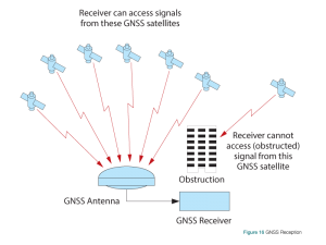
To determine a fix (position) and time, GNSS receivers need to be able to track at least four satellites. This means there needs to be a line of sight between the receiver’s antenna and the four satellites.
Receivers vary in terms of which constellation or constellations they track, and how many satellites they track simultaneously.
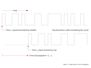
For each satellite being tracked, the receiver determines the propagation time. It can do this because of the pseudorandom nature of the signals. To illustrate, refer to Figure 17, which shows the transmission of a pseudorandom code, a series of zeroes and ones. Since the receiver knows the pseudorandom code for each satellite, it can determine the time it received the code from a particular satellite. In this way, it can determine the time of propagation.
Importance of Antenna Selection
An antenna behaves both as a spatial and frequency filter, therefore, selecting the right GNSS antenna is critical for optimizing performance. An antenna must match the receiver’s capabilities and specifications, as well as meet size, weight, environmental and mechanical specifications for the intended application.
1. Constellation and Signals
Each GNSS constellation has its own signal frequencies and bandwidths. An antenna must cover the signal frequencies transmitted by the constellation and bandwidth supported by the GNSS receiver.
2. Antenna Gain
Gain is a key performance indicator of a GNSS antenna. Gain can be defined as the relative measure of an antenna’s ability to direct or concentrate radio frequency energy in a particular direction or pattern. A minimum gain is required to achieve a minimum carrier- to-power-noise ratio (C/No) to track GNSS satellites. The antenna gain is directly related to the overall C/No of the navigation GNSS receivers. Hence, antenna gain helps define the tracking ability of the system.
3. Element Gain
The element gain defines how efficient the antenna element is at receiving the signals. In any signal chain, you are only as good as the weakest link, so an antenna element with low element gain might be compensated by an increased low noise amplifier gain. The signal-to-noise ratio or C/No, however, is degraded.
4. Antenna Beamwidth and Gain Roll-Off
Gain roll-off is a factor of beamwidth, and specifies how much the gain changes over the elevation angle of the antenna. From the antenna’s point of view, the satellites rise from the horizon towards zenith and fall back to the horizon. The variation in gain between zenith (directly overhead) and the horizon is known as the gain roll-off. Different antenna technologies have different gain roll-off characteristics.
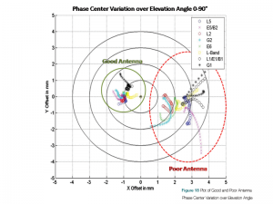
5. Phase Center Stability
The phase center of the antenna is the point where the signals transmitted from satellites are collected. When a receiver reports a location fix, that location is essentially the phase center of the antenna.
The electrical phase center of any antenna will vary with the position of the transmitting signal it is receiving by as much as a few millimetres. As GNSS satellites move across the sky, the electrical phase center of the signal received will typically move with the satellite position unless the antenna has been carefully designed to minimize Phase Center Offset (PCO) and Phase Center Variation (PCV). The PCO, with respect to the Antenna Reference Point (ARP), is the difference between the mechanical center of antenna rotation and electrical phase center location. The PCO is also frequency dependent which means that there can be a different offset for each signal frequency. The PCV identifies how much the phase center moves with respect to the satellite elevation angles.
Many users can accept accuracies of less than a metre so these small phase center variations cause a negligible amount of position error. But if you require high precision, such as Real Time Kinematic (RTK) receivers that can achieve position accuracies of 2-4 cm, a few millimetres of phase center error can translate to a 10-15% error in reported position. For RTK survey applications, geodetic grade antennas offer superior PCO/PCV performance.
6. Application
An antenna has to meet the performance, environmental, mechanical and operational requirements of the intended application. For example, GNSS antennas used for aviation applications should ideally be TSO/FAA certified and be rugged enough to handle extreme temperatures and vibration profiles. Survey rover antennas should be able to survive rough handling by surveyors including a pole drop.
Table 1 highlights some of the important desirable features needed for a GNSS antenna based upon the user’s application.
Survey |
GIS |
Reference Station |
Aviation/Aerial Survey |
Marine |
Construction/Mining |
Precision Agriculture |
Vehicle Tracking |
Dock Operation |
Unmanned Aircraft |
Unmanned Vehicle |
Timing |
|
Low Profile |
• | • | • | • | ||||||||
Ultra-Low PCO/PCV |
• | • | ||||||||||
Low PCO/PCV |
• | • | • | • | • | • | ||||||
High Vibration |
• | • | • | • | • | • | ||||||
Rugged |
• | • | • | • | • | |||||||
Single Frequency |
• | |||||||||||
Multi-Constellation |
• | • | • | • | • | • | • | • | • | • | ||
Multi-Frequency (RTK) |
• | • | • | • | • | • | • | • | • | |||
L-Band Frequency (Correction Services) |
• | • | ||||||||||
Narrow Bandwidth |
• | |||||||||||
Weatherproof |
• | • | • | • | • | • | • | • | • | • | • | • |
Corrosion Resistance |
• | • | • | • | • | |||||||
High Multipath Suppression |
• | • | • | • | • | • | • | |||||
Pole Mount |
• | • | • | • | • | • | • | |||||
Magnetic/Surface Mount |
• | • | • | • | • | |||||||
TSO/FAA Certification |
• | • | ||||||||||
Extended Temperature Range |
• | • | • | |||||||||
Small Form Factor/Low Weight |
• | • | ||||||||||
High Altitude Operation |
• | • | • |