1. Overview
This application note provides an overview of NovAtel‟s ALIGN family of heading solutions, including the ALIGN Heading and ALIGN Relative Positioning models. Receiver hardware setup and software configurations are also discussed.
Heading information can be logged from NovAtel‟s OEM6® receivers at a maximum rate of 20 Hz, or at a maximum of 10 Hz on OEMV® receivers. The Master receiver position accuracy can be enhanced by adding L-Band corrections, SBAS tracking, or by adding an optional RTK static base station.
Please see section 3.1.2 for information regarding ALIGN use with SPAN INS.
2. ALIGN Models
There are two available ALIGN models:
ALIGN Heading provides angular heading and pitch measurements. The following logs are available from any free port:
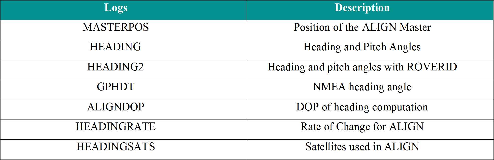 Table 1: ALIGN Heading Logs
ALIGN Relative Positioning provides angular heading and pitch measurements, precise relative positioning measurements and relative baseline information with centimetre level accuracy. The following logs are available from any free port:
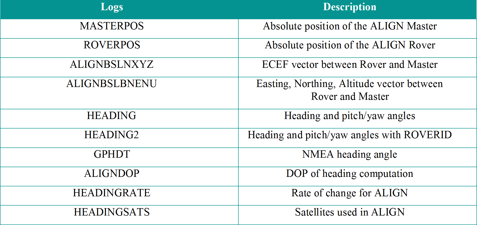 Table 2: ALIGN Relative Positioning Logs
Complete explanation of logs can be found in the OEM6 Firmware Reference Manual.
1. ALIGN Setup (For both models)
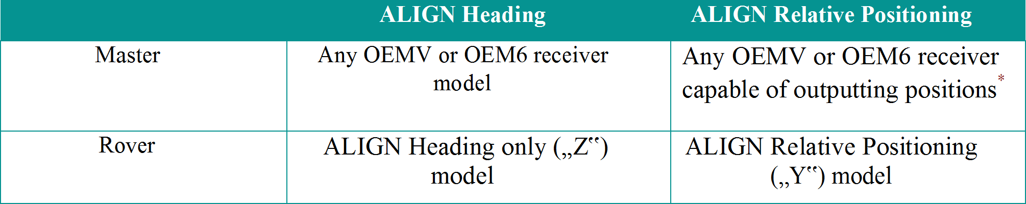
ALIGN functionality requires one receiver to operate as Master to send information to the Rover. The following are the requirements for both ALIGN models:
Receiver features may be limited if basic Position Velocity Time (PVT) only models are used. See Appendix A for more information.
A typical ALIGN setup includes:
- One NovAtel OEM6 or NovAtel OEMV receiver running an ALIGN enabled receiver model and firmware version. This is the Rover receiver.
- One NovAtel OEM6 or NovAtel OEMV receiver. This is the Master receiver.
- Two GPS or GPS+GLONASS capable antennas.
- Data communication link between both receivers. Examples include a radio, modem or serial cable. It is recommended to set the communication rate to 230400 bits per second on both receivers.
* If using an ALIGN Master not capable of outputting a position (i.e: heading only model), ALIGNBSLNXYZ will be available but MASTERPOS, ROVERPOS, and ALIGNBSLNENU will not be.
There are two ways of initializing ALIGN:
i. Plug and Play: ALIGNAUTOMATION command is used at the Rover receiver to setup ALIGN

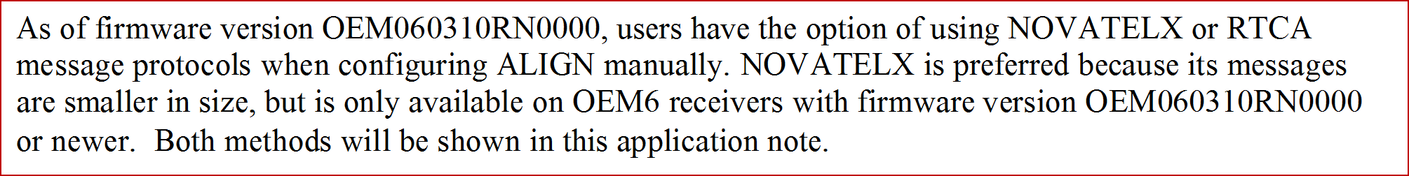
ii. Manual configuration: ALIGN commands are manually sent to the Master and Rover receivers
3. Use Cases
A variety of symbols are used in this application note to depict ALIGN output symbols. The meaning of each symbol is given below.
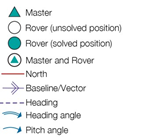 Figure 1: Use Case Legend
1. Use Case 1: Fixed Antenna Distance between Master and Rover Receivers on One Platform (ALIGN Heading)
This use case requires one Master and one Rover receiver. Figure 2 provides an example where the Master and Rover are located on the same vehicle, and the two antennas are located at a fixed distance from one another. Relative heading and pitch are computed with respect to the Master receiver.
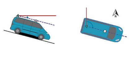 Figure 2: Heading from two receivers on one vehicle
There are two possible ways to set up ALIGN in this use case:
Plug and Play with Cable:
- Connect COM2 of the Rover receiver to an available COM port on the Master receiver using a NULL modem cable.
- Initiate ALIGN from the Rover receiver by entering the following command: ALIGNAUTOMATION ENABLE COM2 230400
- To access heading data, ALIGN logs can be logged at either the ALIGN Master or Rover receiver.
Manual Configuration with Cables:
- Connect any COM port on the Master receiver (e.g. COM2) to any COM port on the Rover receiver (e.g. COM2) using a NULL modem cable.
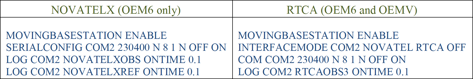
- Issue the following commands to the Master receiver:
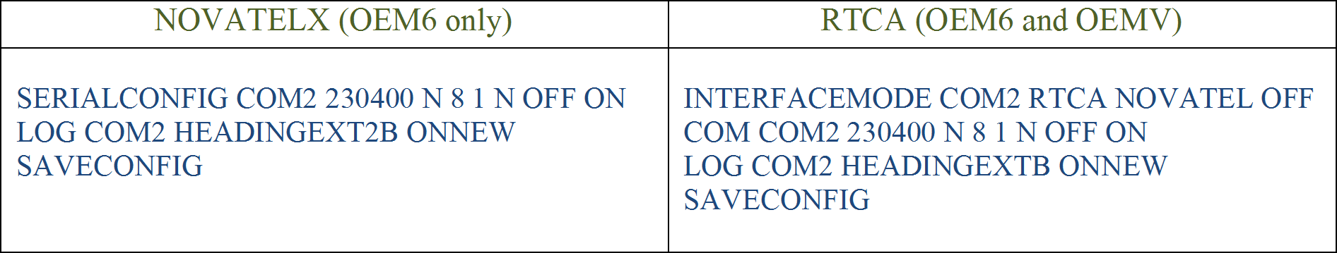
- Issue the following commands to the Rover receiver:
- To access heading data, ALIGN logs can be logged at either the ALIGN Master or Rover receiver.

Manual Configuration through Ethernet:
Many customers use Ethernet due to the fact that one physical connection provides three high speed ports. This section will go through the steps that are needed in order to setup ALIGN through Ethernet. Please note the ALIGNAUTOMATION command does not work with an Ethernet connection.
- Connect your computer to both Master and Rover receivers using null modem serial cables or USB cables.
- Establish a connection to both Master and Rover receivers using either NovAtel Connect or another terminal program such as Windows HyperTerminal. This connection is used to send the commands to the receivers.
- Establish an Ethernet connection on both Master and Rover receivers.
- Dynamic IP Address Configuration
- Connect the Ethernet port of the Master and Rover receivers to the DHCCP server using two patch cables.
- Enable the Ethernet port by entering the following command on both the Master and Rover receivers:
ETHCONFIG ETHA AUTO AUTO AUTO NORMAL - Obtain the IP address assigned to the Master receiver by the DHCP server through the command shown below. Make a note of the IP address returned with this log as it will be used later on. This is only done at the Master.
LOG IPSTATUS ONCE - Confirm that DHCP is enabled by entering the following command. This is done at both the Master and Rover receivers.
LOG IPCONFIG ONCE - Assign the TCP/IP port number by entering the command below. This is only done at the Master.
ICOMCONFIG ICOM1 TCP :3001 - Confirm the port number assigned to the Master‟s ICOM1 by entering the following command at the Master.
LOG ICOMCONFIG ONCE
- Static IP Address Configuration
- Connect the Ethernet port of the Master receiver with the Ethernet port of the Rover receiver using a cross-over cable.
- Enable the Ethernet port by entering the following command on both the Master and Rover receivers:
ETHCONFIG ETHA AUTO AUTO AUTO AUTO - Assign the TCP/IP port number by entering the command below. This is done only at the Master receiver.
ICOMCONFIG ICOM1 TCP :3001 - Assign the receiver IP address, subnet mask, and default gateway of the Master by entering the following at the Master receiver:
IPCONFIG ETHA STATIC 192.168.74.10 255.255.255.0 192.168.74.1 - Assign the receiver IP address, subnet mask, and default gateway of the Rover by entering the following at the Rover receiver:
IPCONFIG ETHA STATIC 192.168.74.15 255.255.255.0 192.168.74.1 - Confirm TCP/IP configuration by entering the following command. This is done at both the Master and Rover receivers.
LOG IPCONFIG ONCE
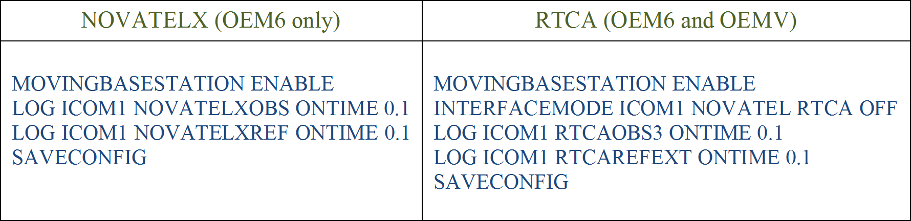
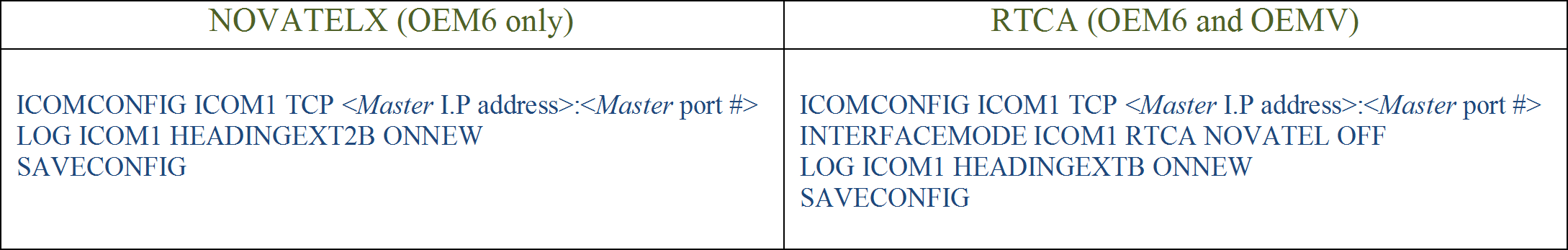
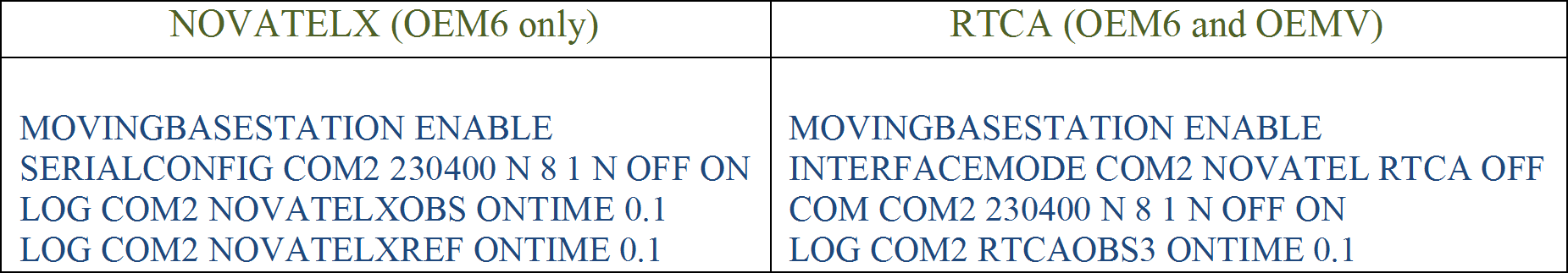
- Send the following commands to the Master receiver. Recall that manual ALIGN configuration can be done either through NOVATELX or RTCA message protocols.
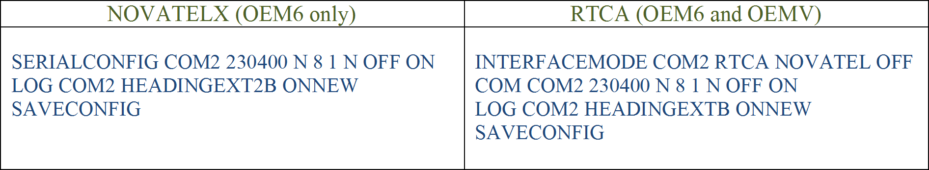
- Send the following commands to the Rover receiver. Recall that manual ALIGN configuration can be done either through NOVATELX or RTCA message protocols.
2. Using ALIGN with SPAN
Please ignore this section if you are not using ALIGN with SPAN INS.
ALIGN configuration when using SPAN is done automatically in the background provided both primary and secondary lever arm has been issued and that the ALIGN rover is connected to the SPAN receiver via serial COM ports. Please refer to the DUALANTENNAPORTCONFIG command in the SPAN firmware reference manual as it specifies the serial COM port from which the SPAN receiver expects connectivity with the ALIGN receiver.
There is one use case that requires further user input and that is if the SPAN and ALIGN rover receivers are connected via Ethernet. If so, please do as follows:
- Setup ALIGN manually using the static IP configuration shown in the previous section.
- Send the following command at the rover: SETROVERID DUAL. Please note the field “DUAL” is case sensitive.
To confirm ALIGN is working and that the heading is being fed into SPAN:
- Send the LOG HEADING command in the SPAN receiver. If nothing is output then something is wrong with the ALIGN configuration.
- Once the SPAN system is configured and has completed alignment (SPAN initialization), the log INSUPDATE can be used to confirm SPAN is using the ALIGN heading. If so, the last field should indicate ACTIVE/USED such as in the example below:
INSUPDATE SPECIAL 0 48.0 FINESTEERING 1701 156566.000 00004000 6f07 10883
SINGLE 0 12 0 FALSE INACTIVE USED
Note that in order for the heading to be fed into the INS the following conditions must be met:
- SETROVERID is set to DUAL
- RTK status in HEADING log (third to last field) is set to RTK verified „01‟
These conditions are important as it is entirely possible to be producing new HEADING logs but they are not being used by the INS filter. Confirmation is done through the LOG INSUPDATE message indicated earlier.
1. Use Case 2: Master and Rover Receivers on Separate Moving Platforms
This use case requires one Master and one Rover receiver. Figure illustrates the Master receiver on the vessel and the Rover receiver located on the fighter jet. Relative heading, pitch, baseline length, and Rover positions are computed with respect to the Master receiver.
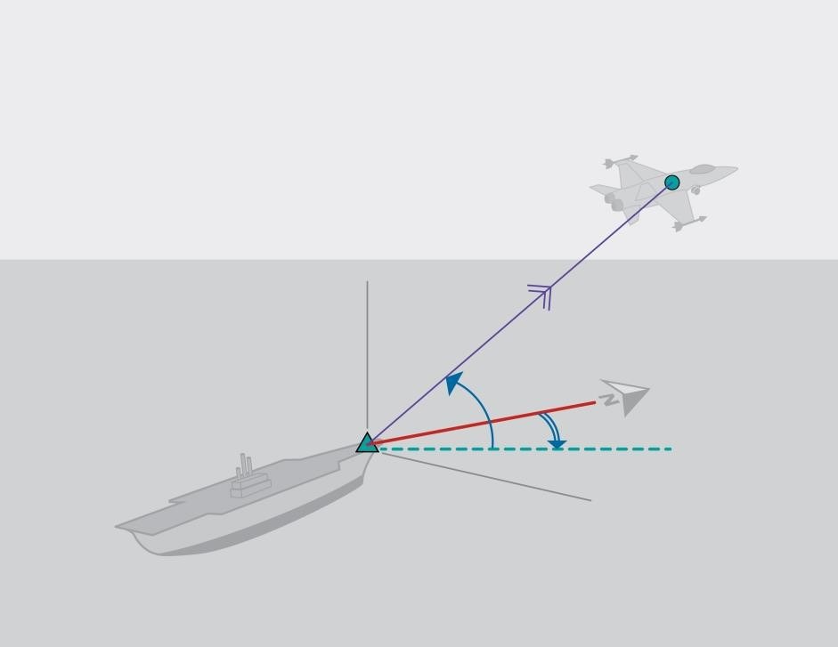 Figure 3: Heading from two receivers on separate platforms
There are two possible ways to set up this use case. One is to take advantage of ALIGN‟s plug and play functionality and another requires manual receiver configuration.
Plug and Play with Wireless Data Link:
- Configure the wireless data links for two-way communication, using the same baud rate (i.e. 230400 bps).
- Connect one wireless data link to an available COM port on the Master receiver.
- Configure the Master receiver‟s COM port to communicate at the same baud rate as the wireless data link using the COM command:
COM COM2 230400 N 8 1 N OFF ON - Connect the other wireless data link to COM2 of the Rover receiver.
- Initiate ALIGN from the Rover receiver by entering the following command:
ALIGNAUTOMATION ENABLE COM2 230400
Manual Configuration with Wireless Data Link:
- Configure the wireless data links for two-way communication, using the same baud rate (230400 bps for this example).
- Connect one wireless data link to an available COM port on the Master receiver (e.g. COM2).
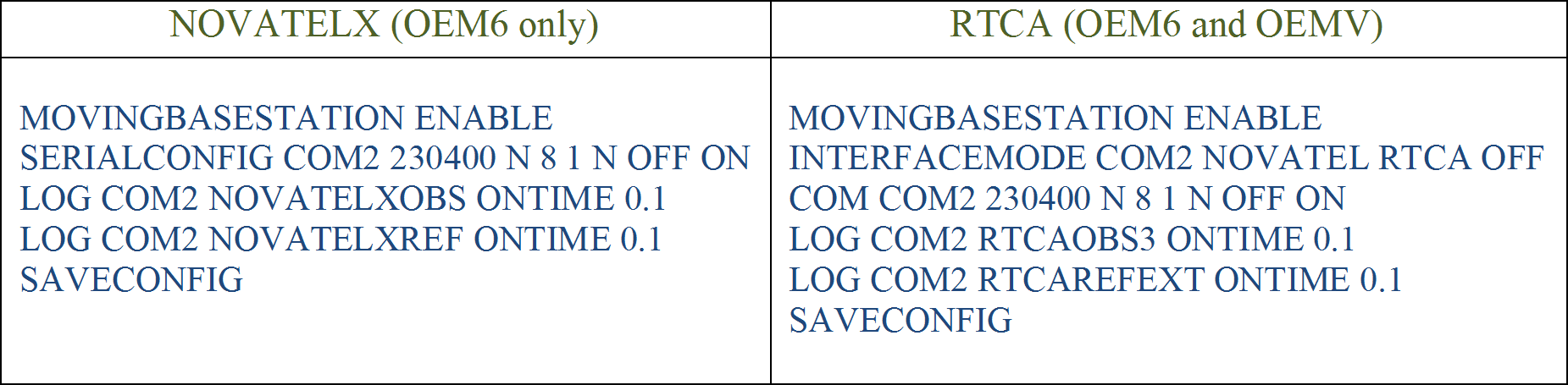
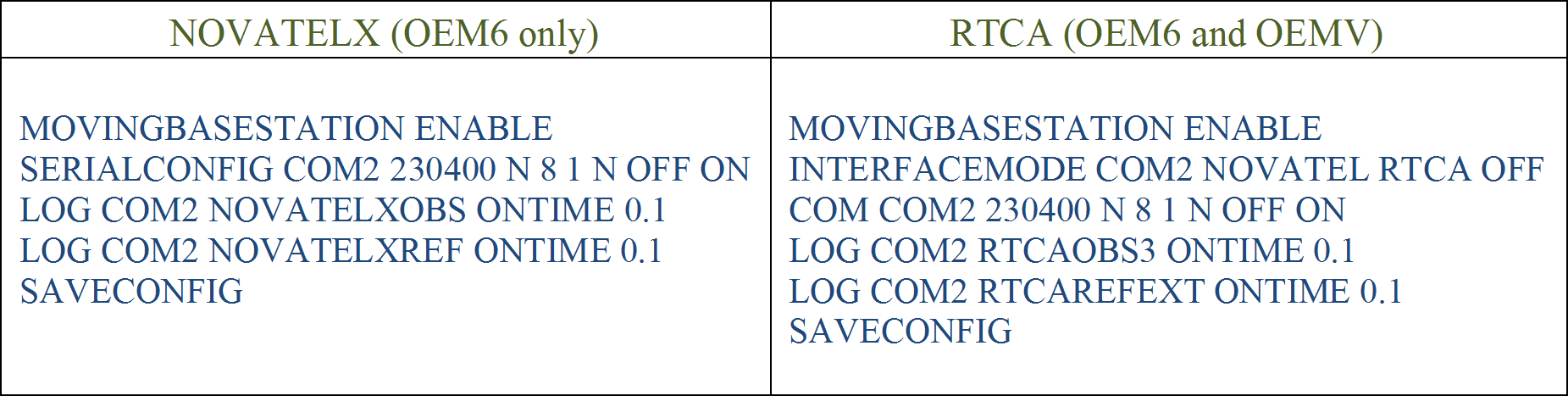
- Configure the Master receiver to output NOVATELX or RTCA corrections at the same baud rate as the wireless data link:
- Connect the other wireless data link to an available COM port (e.g., COM2) on the Rover receiver.
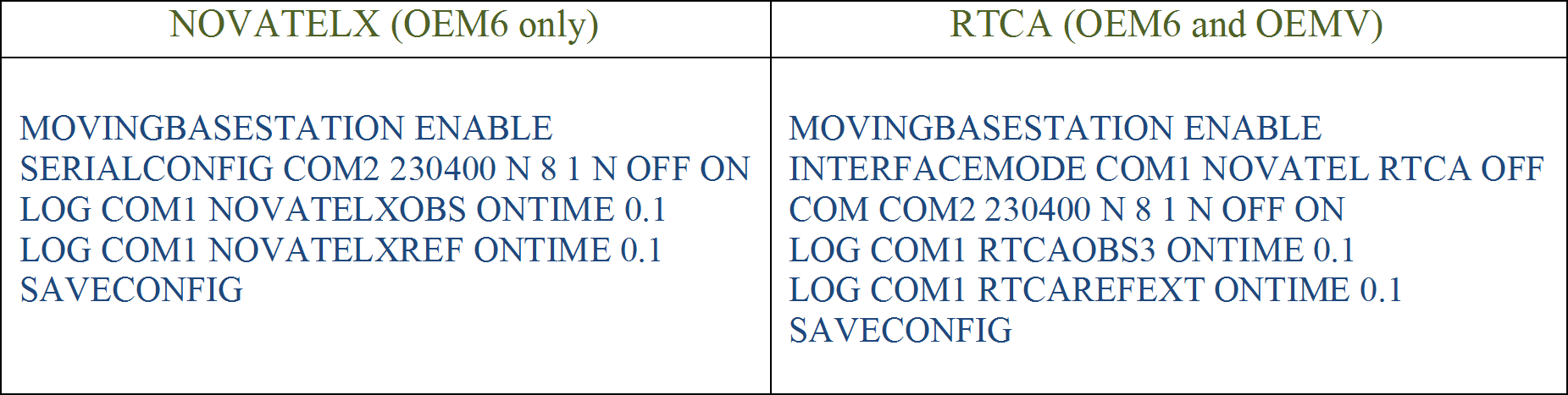
- Configure the COM port (COM2 in this example) of the Rover receiver to receive corrections and output heading information at the same baud rate as the wireless data link:
- To access heading and relative positioning data, ALIGN logs can be logged at either the ALIGN Master or Rover receiver.

1. Use Case 3: Daisy-Chain ALIGN setup
This use case illustrates multiple Master and Rover receivers in a daisy chain type setup. There is one main Master receiver on one platform as a moving reference, with multiple Rovers setup on other platforms. Each Rover can act as the Master receiver for the next Rover receiver by transmitting ALIGN corrections to the next receiver.
Figure 4 illustrates the main Master receiver on a seismic research vessel. The Rover receivers are located on a series of buoys, with each Rover receiver acting as a Master for the next receiver. Relative heading and pitch are computed with respect to its linking Master receiver.
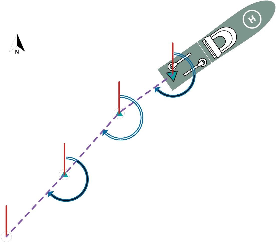 Figure 4: Use Case #3 – Daisy-Chain ALIGN setup
Plug and Play with Wireless Data Link:
- Configure the wireless data links between each Master and Rover pair for two-way communication, using the same baud rate (230400 bps for this example).
- Connect one wireless data link to an available COM port (e.g. COM2) on the first Master receiver.
- Configure the Master receiver COM port to communicate at the same baud rate as the wireless data link using the COM command:
COM COM2 230400 - Connect the other wireless data link to COM2 of the Rover receiver.
- Initiate ALIGN by entering the following command to the Rover receiver:
ALIGNAUTOMATION ENABLE COM2 230400 10 OFF - Configure COM1 of the Rover receiver to send corrections to the next Rover receiver. Connect a wireless data link to COM1 and configure COM1 to communicate at the same baud rate as the wireless data link using the COM command:
COM COM1 230400 - Connect the other wireless data link to COM2 of the next Rover receiver.
- Repeat steps 5 to 7 using the appropriate COM ports until all receivers have been configured
- To access heading and relative positioning data, ALIGN logs must be logged at each ALIGN Rover.
Manual Configuration with Wireless Data Link:
- Configure the wireless data links between each Master and Rover pair for two-way communication, using the same baud rate (230400 bps for this example).
- Connect one wireless data link to an available COM port (i.e., COM2) on the first Master receiver.
- Configure the Master receiver COM port to output corrections at the same baud rate as the wireless data link:
- Connect the other wireless data link to COM2 of the Rover receiver.
- Configure COM2 of the Rover receiver to receive corrections at the same baud rate as the wireless data link:
- Configure COM1 of the Rover receiver to send corrections to the next Rover receiver. Connect a wireless data link to COM1.
- Set the Rover‟s COM1 to output corrections at the same baud rate as the wireless data link:
- Configure COM2 of the next Rover receiver to receive corrections as described in steps 4 and 5.
- Repeat steps 4 to 8 using the appropriate COM ports until all receivers have been configured
- To access heading data, ALIGN logs must be logged at each ALIGN Rover.

1. Use Case #4: Single Master with Multiple Rovers ALIGN setup (ALIGN Relative Positioning)
This use case demonstrates one ALIGN Master and multiple Rover receivers. There is one main Master receiver set up on one platform as a moving reference, with multiple Rovers set up on other platforms.
Figure 4 illustrates the main Master receiver on a seismic research vessel. The Rover receivers are located on a series of buoys. Relative heading, pitch, baseline length and Rover positions are computed with respect to the Master receiver.
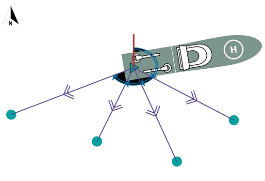 Figure 5: Single Master with Multiple Rovers ALIGN Setup
Manual Configuration with Wireless Data Link:
- Configure the wireless data links for two-way communication, using the same baud rate (e.g. 230400 bps).
- Connect one wireless data link to an available COM port on the Master receiver (e.g. COM2).
- Configure the Master receiver to output corrections at the same baud rate as the wireless data link:
- Connect the other wireless data link to an available COM port on the Rover receiver.
- Configure Rover receiver to receive corrections and output heading information at the same baud rate as the wireless data link:
- Repeat steps 4 and 5 until all Rover receivers are configured.
- To access heading and relative positioning data, ALIGN logs can be logged at each ALIGN Rover, or alternatively, data for all Rovers can be accessed at the Master receiver.

1. Use Case #5: Star Configuration
This case demonstrates one ALIGN Master setup between two Rover receivers. Only the Master receiver has to maintain a connection with the computer throughout data collection.
Figure 6 illustrates the Master receiver and Rover1 receiver on a back of the truck and Rover2 receiver on the front part of the truck. Relative heading, pitch, and rover positions are computed with respect to the Master.
In the example shown in Figure 7, Rover1 is connected to the Master through COM1 while Rover2 is connected to the Master through COM2. COM2 of Rover1 and COM1 of Rover2 are only used initially to setup the rovers through the computer. The Master receiver is connected to the computer via USB port (can also be Ethernet).
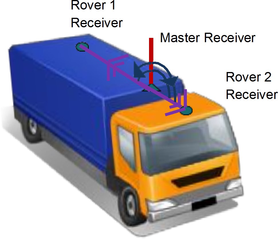 Figure 6: ALIGN Star Configuration Scenario
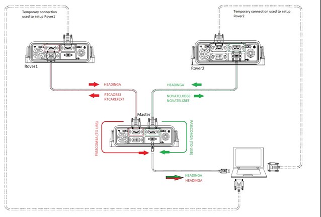 Figure 7: ALIGN Star Configuration Setup Example
Star Align Setup and Configuration:
This example is applicable for OEM 6 receivers.
- Establish communication with the Master receiver (via USB port or Ethernet).
- Establish communication with the Rover1 receiver (via COM2).
- Establish communication with the Rover2 receiver (via COM1).
- Connect the Rover1 receiver to the Master receiver using COM 1 port.
- Connect the Rover2 receiver to the Master receiver using COM2 port.
- Issue the following commands to the Master:
MOVINGBASESTATION ENABLE INTERFACEMODE COM1 NOVATEL RTCA OFF
INTERFACEMODE COM2 NOVATEL NOVATELX OFF COM COM1 230400 N 8 1 N OFF ON
COM COM2 230400 N 8 1 N OFF ON LOG COM1 RTCAOBS3 ONTIME 0.1
LOG COM1 RTCAREFEXT ONTIME 0.1 LOG COM2NOVATELXOBS ONTIME 0.1 LOG COM2 NOVATELXREF ONTIME 0.1 SAVECONFIG
- Issue the following commands to Rover1:
INTERFACEMODE COM1 RTCA NOVATEL OFF COM COM1 230400 N 8 1 OFF ON
LOG COM1 HEADINGA ONCHANGED SAVECONFIG
- Issue the following commands to the Master. The heading from Rover1 should be received at the computer at this point.
LOG PASSCOM1A ONCHANGED SAVECONFIG - Issue the following commands to Rover2:
INTERFACEMODE COM2 NOVATELX NOVATEL OFF COM COM2 230400 N 8 1 N OFF ON
LOG COM2 HEADINGA ONCHANGED SAVECONFIG - Issue the following commands to the Master. The heading from Rover2 should be received at the computer at this point.
LOG PASSCOM2A ONCHANGED SAVECONFIG
A: Model Compatibility Chart 4
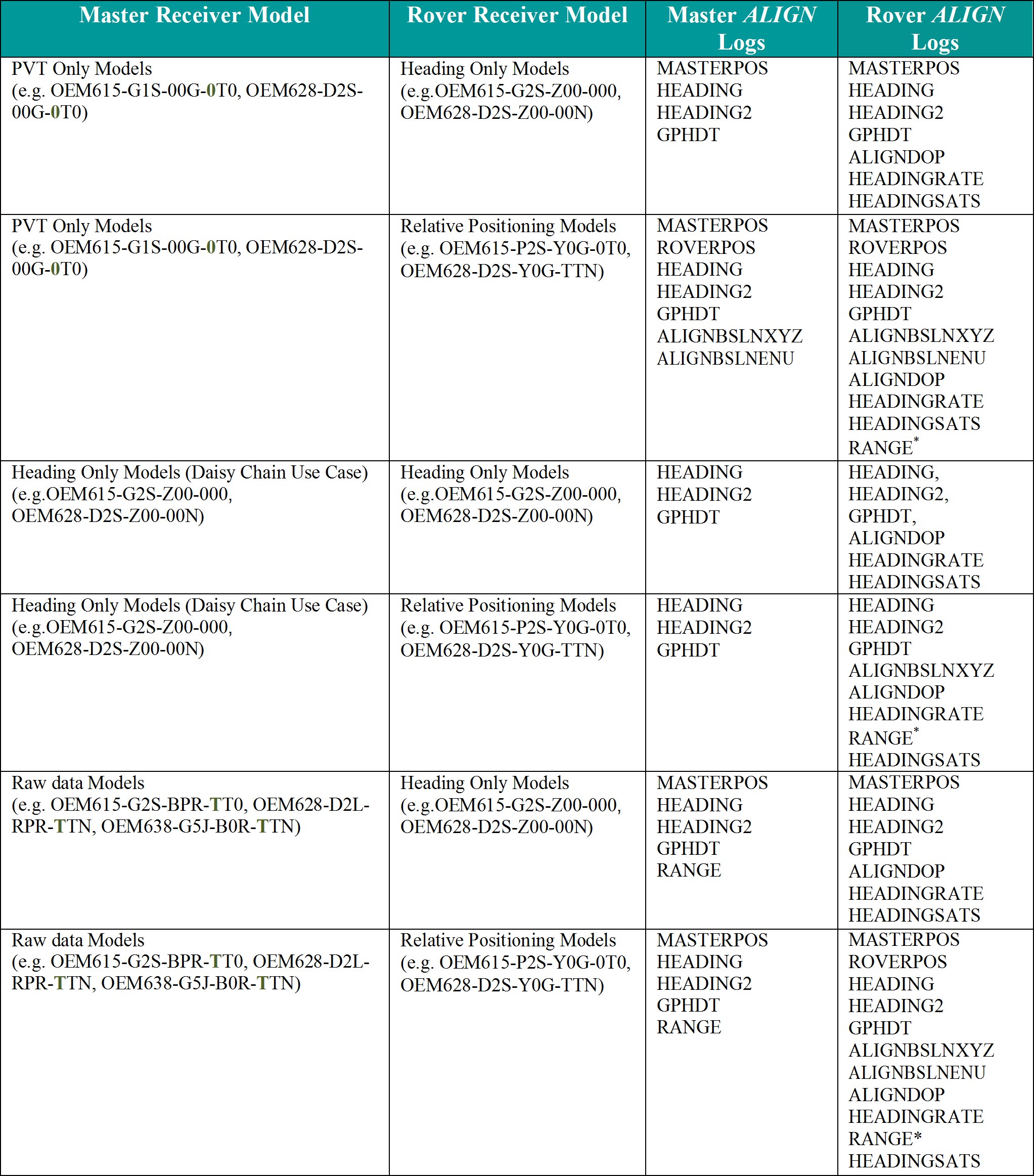
See Appendix B for link to receiver model configurations
* Available with raw data models
B: Receiver Model Configuration Descriptions
Refer to NovAtel product model list for complete list of ALIGN capable receivers and models. The last page of the model list document contains the possible receiver model configuration descriptions.
C: Dual Antenna Products
Dual antenna products such as the SPAN-SE-D, ProPak-6-D, OEM-617D, and FLEXPAK-6D are hardware preconfigured for ALIGN heading. No additional user input is required. Additional setup and equipment will be required if these systems are used in multiple platform applications (e.g. daisy chain use case, master and rover on separate moving platform use case, and single master with multiple rovers use case).