Chapter 1 Overview
NovAtel offers GNSS antennas and cables tailored for use with NovAtel GNSS receivers. These accessories provide for both easy installation and optimal operation. However, as the receivers are designed to meet the needs of a wide range of applications, the use of non-NovAtel accessor- ies for a unique installation may be desired. This application note provides information on the standard NovAtel configuration, as well as recommendations for meeting the receiver’s RF input requirements in special cases. In addition, information on obtaining the equipment required for such cases is provided.
A variety of symbols are used in this application note to depict equipment configurations and characteristics. The meaning of each symbol is given below.
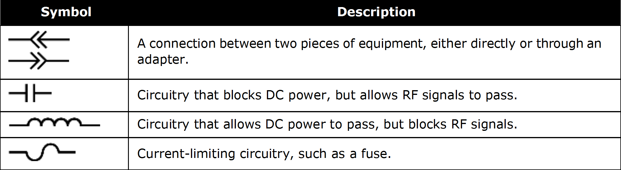 Table 1: Symbol Legend
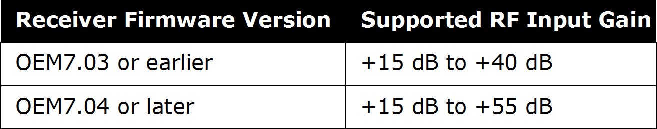
1.1 Receiver Input Gain Requirements
The RF input gain supported by NovAtel's OEM7 GNSS receiver depends on the firmware version running on the receiver.
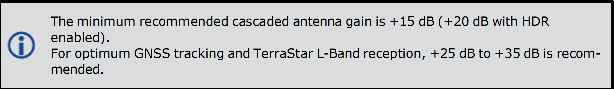
For optimum GNSS tracking and TerraStar L-Band reception, a cascaded antenna gain of +25 dB to +35 dB is recommended.

NovAtel sells a variety of RF cables ranging in length from 8.5 cm to 30 meters. The following table shows the typical signal power loss of these RF cables in dB.
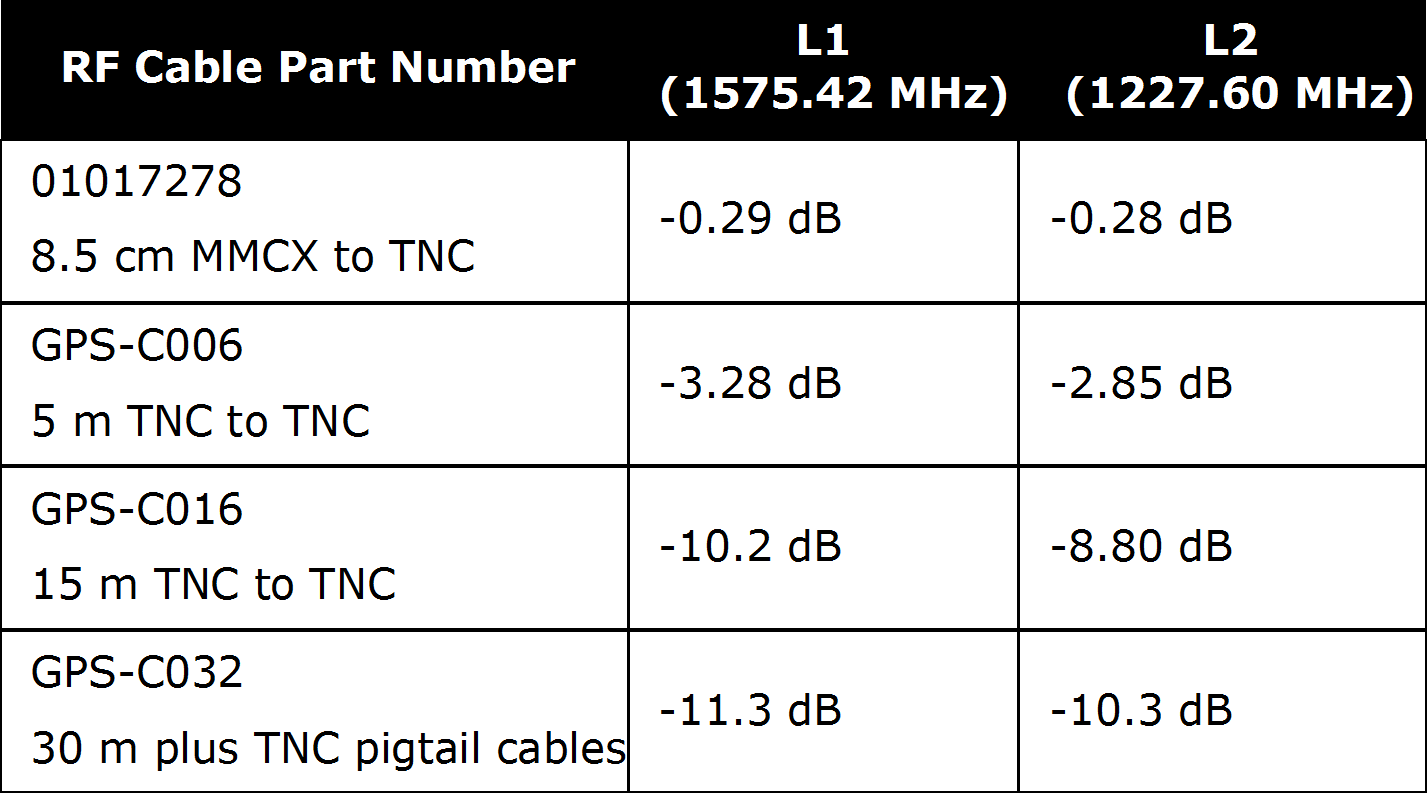 Table 2: NovAtel RF Cable Loss Figures
Using NovAtel’s GNSS antennas and coaxial cables, the GNSS receiver’s requirement for +15 dB to +40 dB gain from the antenna, including the antenna element, LNA and cable, at its RF input is easily met. All NovAtel GNSS antennas employ a built-in, low-noise amplifier (LNA), which typ- ically provides +25 to +35 dB of gain to the GNSS satellite signal. The power to the antenna LNA is provided through the center conductor of the receiver’s RF port.
RF Equipment Configuration below shows a standard antenna cable configuration using NovAtel’s 5 metre, ~3 dB loss RF cable and a GNSS antenna with a +29 dB gain LNA.
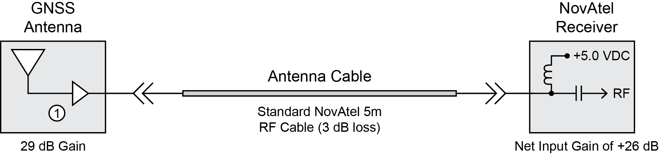 Figure 1: Standard NovAtel RF Equipment Configuration
The antenna LNA is powered by +5.0 VDC from the receiver via the antenna cable center conductor.
For a specialized application or custom installation, GNSS antennas and coaxial cables other than those offered by NovAtel may be preferred. In these cases, extra care must be taken to ensure the RF equipment being used meets the receiver’s RF input signal range requirements. The sections that follow provide recommendations for special cases that may occur with the use of non-NovAtel accessories, as highlighted in the Table 3: Special Cases below.
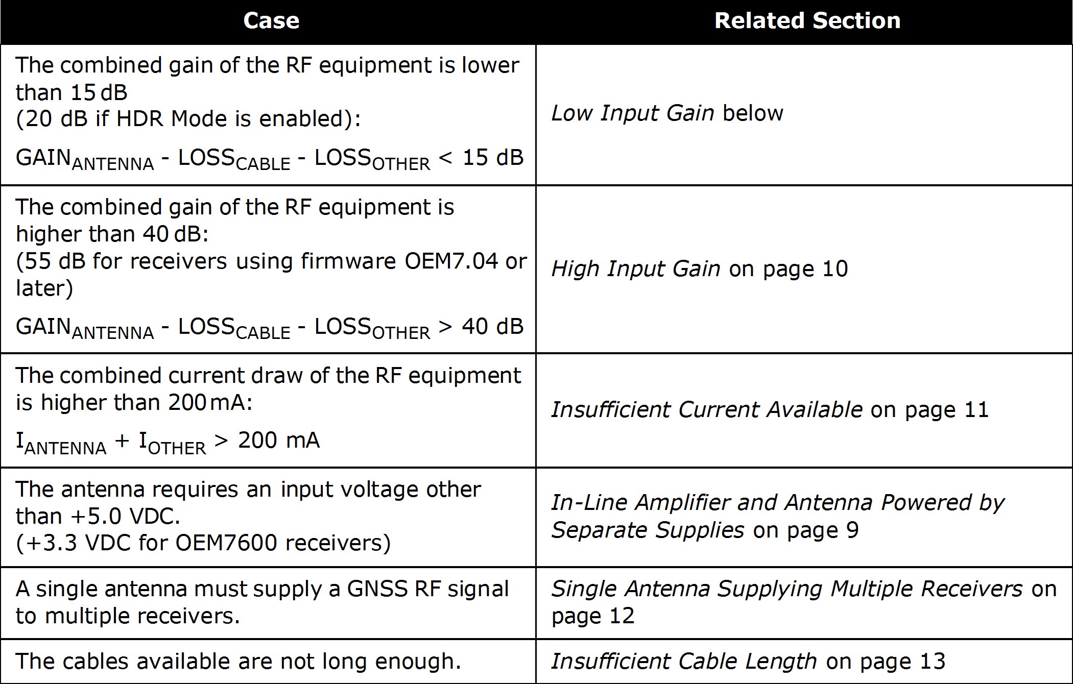 Table 3: Special Cases
1. Low Input Gain
If the cable loss reduces the LNA gain provided by the selected antenna to less than 15 dB (20 dB if HDR Mode is enabled), a low-noise amplifier must be added in-line between the antenna and the receiver. The in-line amplifier must provide sufficient gain to ensure the RF input gain to the receiver is provided within the range described in Receiver Input Gain Requirements on page 3. The in-line amplifier should be installed as close to the GNSS antenna as possible to ensure the GNSS signal is amplified when the signal to noise ratio is at its highest. Depending on the power req
uirements of the amplifier, the configuration of the RF equipment will vary, as shown in the following table.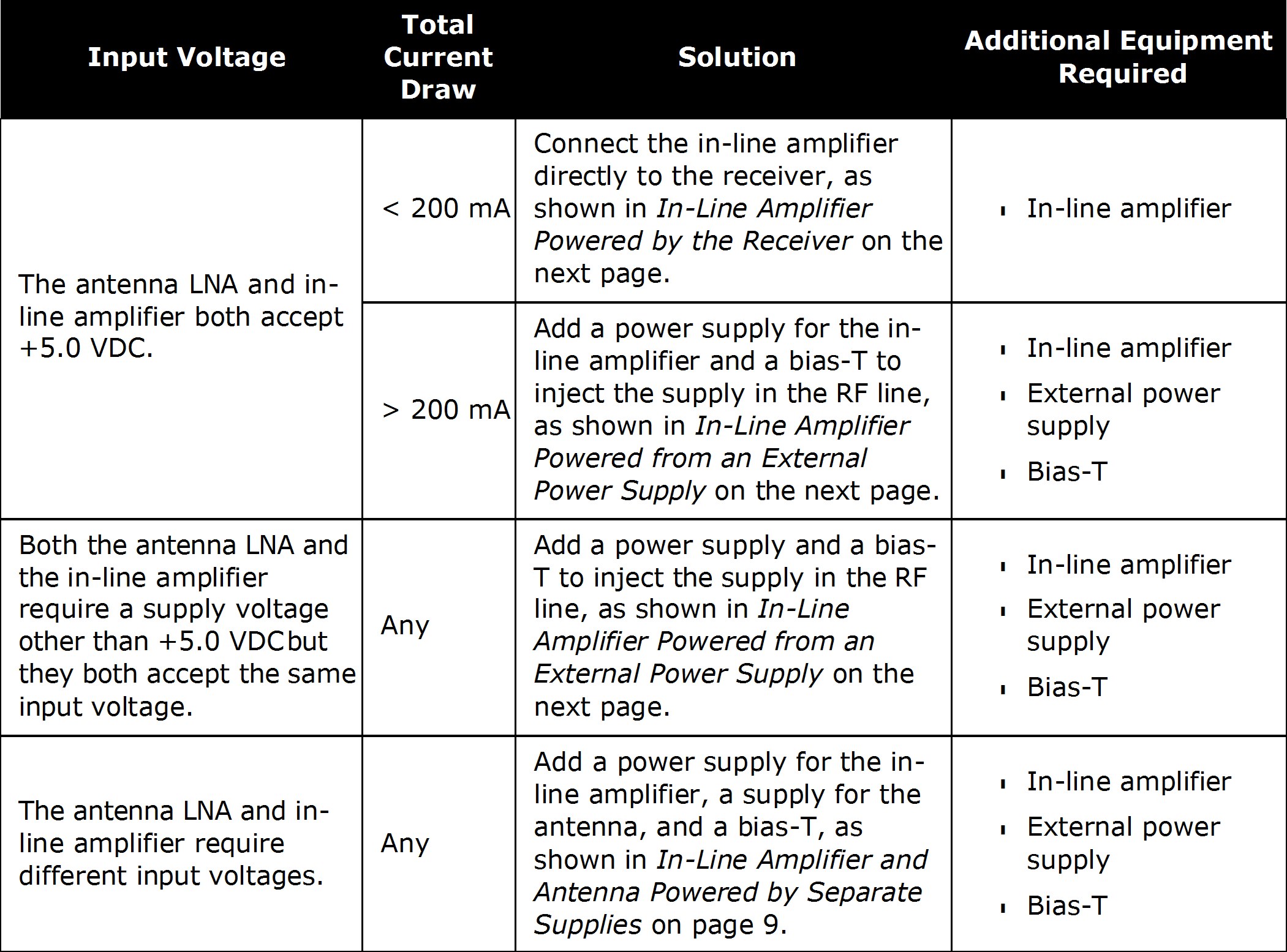 Table 4: Solutions for Low Input Gain based on RF Equipment Power Requirements
Current Requirement
As shown in Table 4: Solutions for Low Input Gain based on RF Equipment Power Requirements above, the total amount of current required by the in-line amplifier and the GNSS antenna LNA is a factor when determining how to set up the RF equipment. NovAtel OEM7 receivers can provide up to 200 mA at +5.0 VDC on the center conductor of the RF port. Therefore, if the combined cur- rent draw of all the RF equipment connected to the port, including the in-line amplifier, is less than 200 mA, the receiver can supply the power.
For example, if the selected antenna’s LNA requires 50 mA and there is no other equipment between the antenna and the receiver that draws current, an in-line amplifier that draws 10 mA can be used without the addition of an external supply.
Amplification Requirement
Select an in-line amplifier that increases the signal gain by the amount necessary to result in an overall gain of +25 dB, as shown in the formula below. Be sure to take into account the loss cre- ated by any additional equipment being used with the in-line amplifier, such as bias-Ts.
AMPLIFICATION = 25 dB + LOSSCABLE + LOSSOTHER - GAINANTENNA
For example, if the selected antenna LNA provides +30 dB gain and the cable has a loss of -20 dB, then +15 dB amplification must be added.
3.1.1 In-Line Amplifier Powered by the Receiver
If the RF equipment draws a total of less than 200 mA, the antenna LNA and in-line amplifier both accept a +5.0 VDC supply, and the inline amplifier is capable of passing the DC power from the receiver, then the equipment can be connected directly to the receiver without the need for an external power supply. Figure 2: In-Line Amplifier Powered by the Receiver below illustrates this configuration.
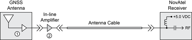 Figure 2: In-Line Amplifier Powered by the Receiver
1. Most GNSS antenna LNAs safely operate with +5.0 VDC input voltage.
2. The in-line amplifier is powered by the +5.0 VDC provided by the receiver. The in-line amplifier is shunt-fed, which allows the DC power to continue to the antenna.
2. In-Line Amplifier Powered from an External Power Supply
Figure 3: In-Line Amplifier Powered by an External Supply on the next page illustrates an in-line amplifier that requires an external power source because the 200 mA provided by the receiver is not enough current. The in-line amplifier is powered directly via the bias-T and coaxial cable, with the DC power continuing on to the GNSS antenna LNA. The bias-T should include circuitry to prevent DC power from being fed back to the receiver and the ANTENNAPOWER OFF command must be issued to disable the GNSS receiver’s internal LNA power supply.


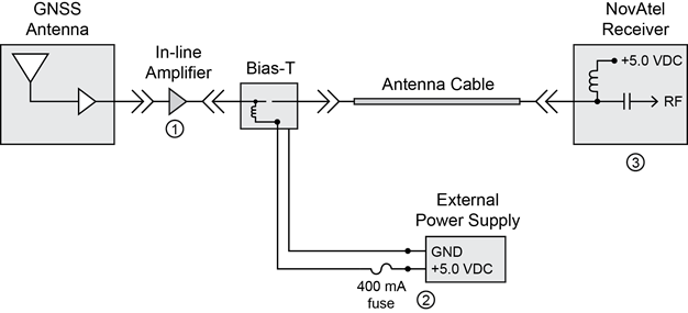 Figure 3: In-Line Amplifier Powered by an External Supply
The in-line amplifier operates from power supplied via the coaxial cable center conductor and is shunt-fed, which allows the DC power to continue down the coaxial cable to the antenna.
The fusing and power supply requirements depend on the in-line amplifier and antenna. 400 mA and +5.0 VDC are examples sh
own for illustration purposes only.The ANTENNAPOWER OFF command must be issued to the receiver to disable the receiver’s internal LNA power output.
2. In-Line Amplifier and Antenna Powered by Separate Supplies
Figure 4: In-Line Amplifier and Antenna Powered by Separate Supplies illustrates a more complicated solution using an in-line amplifier that requires a power source that differs from that required by the antenna. The bias-T should include circuitry to prevent DC power from being fed back and the ANTENNAPOWER OFF command must be issued to disable the receiver’s internal LNA power supply. Since the bias-T is not placed between the in-line amp- lifier and the receiver, DC blocking circuitry must be added between the two.

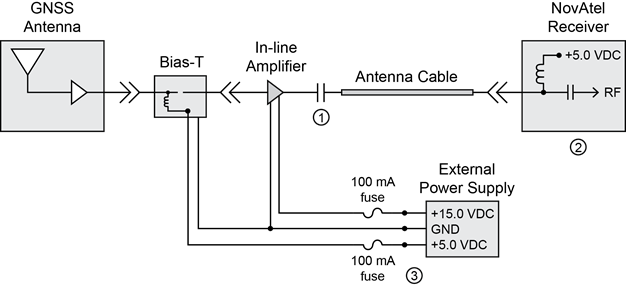 Figure 4: In-Line Amplifier and Antenna Powered by Separate Supplies
Circuitry to block DC power from feeding back to the receiver is required.
The ANTENNAPOWER OFF command must be issued to the receiver to disable the receiver’s internal LNA power output.
The current and voltage requirements of your in-line amplifier and antenna may vary. The fuses and supply voltages shown are for illustration purposes only.
1. High Input Gain
If the antenna LNA gain exceeds the cable loss by more than +40 dB (OEM7.03 or earlier) or +55 dB (OEM7.04 or later), the RF signal must be attenuated before reaching the receiver, as shown in Figure 5: In-Line Attenuator below.
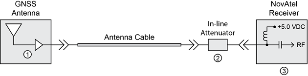 Figure 5: In-Line Attenuator
Most GNSS antenna LNAs safely operate with +5.0 VDC input voltage
The in-line attenuator must allow DC power to continue to the antenna.
The net gain at the RF input should not exceed: +40 dB (OEM7.03 or earlier) +55 dB (OEM7.04 or later)
3.2.1 Attenuation Requirement
In this example, we will select an in-line attenuator that reduces the signal by the amount neces- sary to result in an overall gain of +30 dB, as shown in the formula below. Be sure to take into account the loss created by any additional equipment being used with the attenuator. Install the attenuator as close to the receiver as possible to avoid adding extra noise to the GNSS signal.
ATTENUATION = GAINANTENNA – LOSSCABLE – LOSSOTHER – 30 dB
For example, if the selected antenna LNA provides +70 dB gain and the cable has a loss of -10 dB, a -30 dB attenuator can be added.
3. Insufficient Current Available
NovAtel OEM7 receivers provide up to 200 mA from their RF ports. In cases where the RF equip- ment connected to the RF port consumes more than this amount, an external power supply and bias-T must be added to the installation. The bias-T should include circuitry to prevent DC power from being fed back to the receiver and the ANTENNAPOWER OFF command must be issued to disable the receiver’s internal LNA power supply. A simple installation with an antenna LNA that requires more than 200 mA is shown in Figure 6: External Power Supply to Meet Current Require- ments below.

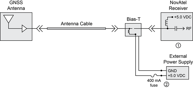 Figure 6: External Power Supply to Meet Current Requirements
1. The ANTENNAPOWER OFF command must be issued to the receiver to disable the receiver’s internal LNA power output.
2. The current and voltage requirements of your RF equipment may vary. The 400 mA fuse and +5.0 VDC supply are for illustration purposes only.
4. Single Antenna Supplying Multiple Receivers
If a single antenna is to be connected to multiple receivers, a splitter must be inserted between the antenna and the receivers. Figure 7: Single Antenna to Multiple Receivers below illustrates a typical setup using a splitter to provide two receivers with the GNSS signal. The splitter is designed so that one of the receivers provides power to the antenna while the other is blocked so no DC power passes from it to the antenna or back to the first receiver.
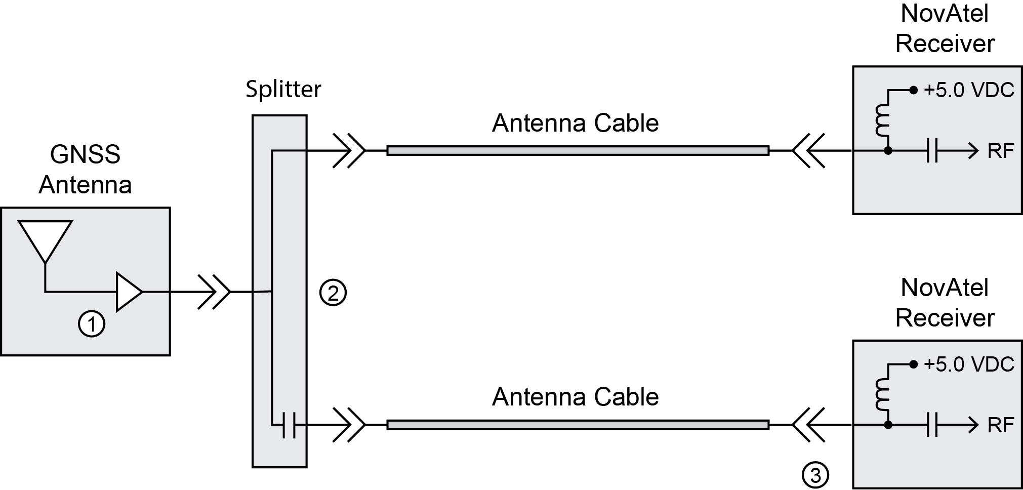 Figure 7: Single Antenna to Multiple Receivers
Most GNSS antenna LNAs safely operate with +5.0 VDC input voltage.
The splitter allows DC power from the top receiver to feed the antenna. It prevents DC power from the bottom receiver from moving to the antenna or back to the top receiver.
The ANTENNAPOWER OFF command must be issued to the receiver that is not powering the antenna to disable the receiver’s internal LNA power output.
If the overall gain at the receiver is less than +15 dB due to the addition of the splitter and any other equipment introduced, an in-line amplifier must be installed between the antenna LNA and the splitter, where the signal to noise ratio is at its highest. For example, if the antenna provides +30 dB of gain, the connection between the antenna and the splitter introduces -5 dB loss, the splitter adds -5 dB loss and the cable between the splitter and receiver reduces the signal by -10 dB, amplification by at least +5 dB is required to yield the minimum input gain requirement of +15 dB; to attain a net RF input gain of +25 dB, then +15 dB of amplification would be required. Figure 8: Single Antenna to Multiple Receivers with In-Line Amplifier on the next page shows an in-line amplifier requiring an external supply and, therefore, a bias-T. The bias-T should include circuitry to prevent DC power from being fed back to the receiver and the ANTENNAPOWER OFF command must be issued to disable the internal LNA power supply on both receivers. See Low Input Gain on page 6 for other installation solutions based on the power requirements of the in- line amplifier.
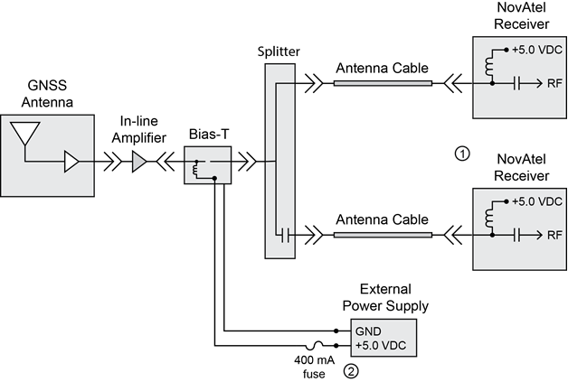 Figure 8: Single Antenna to Multiple Receivers with In-Line Amplifier
The ANTENNAPOWER OFF command must be issued to each of the receivers to disable the receivers’ internal LNA power output.
The fusing and power supply requirements depend on the in-line amplifier and antenna. 400 mA and +5.0 VDC are examples shown for illustration purposes only.
3. Insufficient Cable Length
In some cases, the 30 meter RF cable available from NovAtel is not long enough. There are two basic methods that facilitate longer antenna cable runs:
Selecting specialized low-loss coaxial cables (passive method)
Inserting additional cable lengths and adding in-line, low noise amplifiers between the GNSS antenna, antenna cable, and receiver to keep the net gain at an acceptable level (active method).
1. Passive Cable Runs
The passive method of extending the remote location of the GNSS antenna is achieved by select- ing a high quality coaxial cable exhibiting low loss over extended lengths, as shown in Figure 9: Extended Length, Low-Loss Antenna Cable on the next page. Distances of 200 to 300 metres (656 to 984 feet) are possible by this method. The most important factor in selecting the cable is that its maximum loss over the desired length still provides for at least +15 dB (+20 dB if HDR Mode is enabled), and preferably +25 dB of gain at the receiver’s RF input.
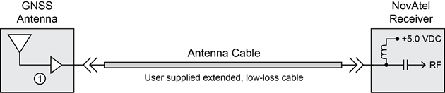 Figure 9: Extended Length, Low-Loss Antenna Cable
The antenna LNA is powered by +5.0 VDC from the receiver via the antenna cable center conductor.
One major disadvantage of specialized low-loss cables for long runs is that typically a larger dia- meter cable is required to reduce the signal losses. This in turn means that heavier, more rigid cable construction is required to manufacture the cable. Weight and flexibility may be a major factor in the practical limit for the cable length. A sharp rise in the cost per metre accompanies low-loss cables since special manufacturing methods and materials are required. Eventually, as distances become greater, a practical limit is reached where cost, weight, and rigidity become prohibitive factors.
2. Active Cable Runs
In some cases, long cable runs may become more practical by using "active" methods. Increas- ing the distance between the GNSS antenna and receiver by active means is accomplished by inserting one or more additional cable lengths and adding an in-line amplifier to negate the sig- nal loss of each additional cable length.
The use of in-line amplifiers allows for smaller, less expensive, and more flexible coaxial cable as opposed to the larger, semi-rigid, low-loss cables. On the other hand, a good deal more hard- ware is required for the installation, such as one or more in-line amplifiers, an external power supply system for the amplifiers and possibly a DC block, coaxial connector adapters, and a bias-T to inject the external power supply through the coaxial cable.
A basic installation using an in-line amplifier powered by an external power supply through a bias-T is shown in Figure 10: Additional Cable Length with In-Line Amplifier on the next page. The bias-T should include circuitry to prevent DC power from being fed back to the receiver. Because an external supply is being used, the receiver’s internal LNA power output must be dis- abled using the ANTENNAPOWER OFF command. However, depending on the power require- ments of the in-line amplifier and antenna, one of the other solutions for incorporating in-line amplifiers as discussed in Insufficient Cable Length on the previous page may be more suitable.

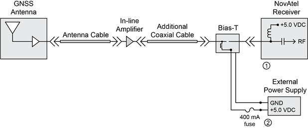 Figure 10: Additional Cable Length with In-Line Amplifier
The ANTENNAPOWER OFF command must be issued to the receiver to disable the receiver’s internal LNA power output.
The current and voltage requirements of your RF equipment may vary. The 400 mA fuse and +5.0 VDC supply shown are for illustration purposes only.
This section provides information on suppliers and equipment that may meet your needs for GNSS antenna installation.

1. Low-Loss Cables
One source of low-loss coaxial cables is the CommScope Corporation. CommScope supplies low- loss HELIAX® cables of various sizes, loss values, and flexibility. To find out more about Com- mScope’s products, visit www.commscope.com.
2. In-Line Amplifiers
Antcom offers inline amplifiers that can be used for an extended cable run or when the RF equip- ment loss is too great to
meet the GNSS receiver’s input gain requirements. For more inform- ation, visit www.antcom.com.Mini-Circuits also offers inline amplifiers. However, typically their in-line amplifiers require 15 VDC and, therefore, the configuration must follow that described in In-Line Amplifier and Antenna Powered by Separate Supplies on page 9. An adapter may also be required, as Mini-Cir- cuit’s in-line amplifiers are typically supplied with BNC or SMA connectors. For further inform- ation, visit www.minicircuits.com.
3. Other Equipment
In addition to providing in-line amplifiers, Antcom also provides splitters, cables and GNSS antennas. For further information, visit www.antcom.com.
Mini-Circuits offers splitters and bias-Ts, as detailed at www.minicircuits.com. Any bias-Ts used should include circuitry to prevent DC power from being fed back to the receiver. GPS Net- working, at www.gpsnetworking.com, specializes in custom parts and in-line TNC attenuators.