Determining Rotations for Inertial Explorer and SPAN
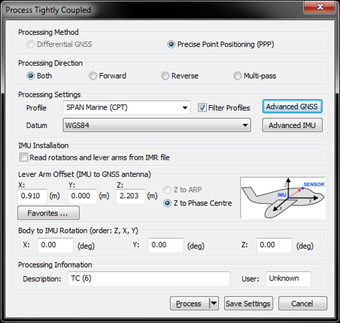
Both Inertial Explorer (IE) and SPAN use intrinsic ZXY-order Euler angles to define the rotation between the IMU and output (vehicle) frames, but each has a different approach to how the user should come up with the input angles. The objective is to determine the rotation from the vehicle to the target frame (IMU).
Whenever possible, mount the IMU without rotations (Y forward, X right, Z up). This will help reduce the possibility for errors caused by incorrectly configured rotations.
Basic Frames
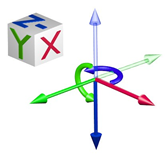
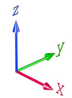
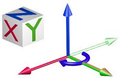
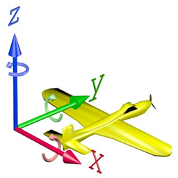 Figure 1: Cartesian coordinate system (Vehicle Frame)
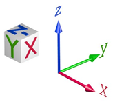
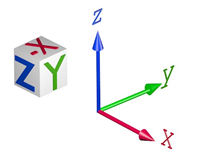
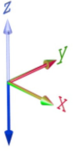
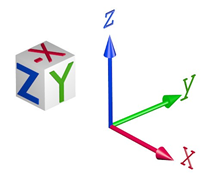
 Figure 2: IMU Frame (Example)
The IMU frame is the objective of the rotations. The rotations are applied to the vehicle frame in the order ZXY until the IMU frame is reached.
The angles are all in a right handed direction. Using your right hand, with your thumb in the direction of the vector, the fingers will curl in the direction of positive rotation.
Inertial Explorer
Start with the vehicle axes (Y forward, X right, Z up).
Rotate around the vehicle Z axis until the vehicle Y axis is in the plane that the IMU Y axis would sweep out if rotated about its X axis (this is your Z input angle).
Z angle
Now rotate around the vehicle X axis until the Y axes match (this is your X input angle).
X angle
Now rotate around the vehicle Y axis until both the X and Z axes match (this is your Y input angle).
Y angle
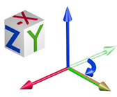
Example 1 (Inertial Explorer): X = 0 Y = 180 Z = 180
In this example, the IMU (target frame) is mounted with its Y axis backwards, X axis to the right and Z axis down. The vehicle frame is Y axis forward, X axis right and Z axis up.
Rotate about Z: Starting from the vehicle frame, rotate first about the Z axis (solid blue)
Z = 180 degrees
Rotate about X: Because the Y axis now matches the IMU there is no need to rotate about X (solid red)
X = 0 degrees
Rotate about Y: Now rotate about the Y axis (solid green) until X and Z match the IMU axes
Y = 180 degrees
Total rotation for input into IE:
X = 0 Y = 180 Z = 180
Example 2 (Inertial Explorer): X = 0 Y = 90 Z = -90
In this example, the IMU (target frame) is mounted with its Z axis backwards, Y axis to the right and X axis down. The vehicle frame is Y axis forward, X axis right and Z axis up.
Rotate about Z: Starting from the vehicle frame, rotate first about the Z axis (solid blue)
Z = -90 (or 270) degrees
Rotate about X: Because the Y axis now matches the IMU there is no need to rotate about X (solid red)
X = 0 degrees
Rotate about Y: Now rotate about the Y axis (solid green) until X and Z match the IMU axes
Y = 90 degrees
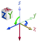
Total rotation for input into IE:
X = 0 Y = 90 Z = -90
SPAN
When logging from SPAN, for use later in IE, be sure to log the following logs along with the standard post processing profile. If logged, IE will automatically populate and use the rotations from the SPAN file.
LOG IMUTOANTOFFSETSB ONCHANGED LOG VEHICLEBODYROTATIONB ONCHANGED
Determining what the vehicle to IMU rotation should be: Start with the physical IMU axes. Determine the mapping:
Which way is up? This defines the mapping during a static alignment. Or with kinematic alignments, which orientation did you set using the SETIMUORIENTATION command?
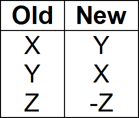
IMU Mapping
Table 1: Mapping
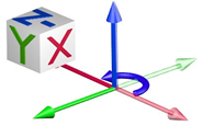
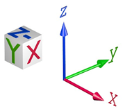
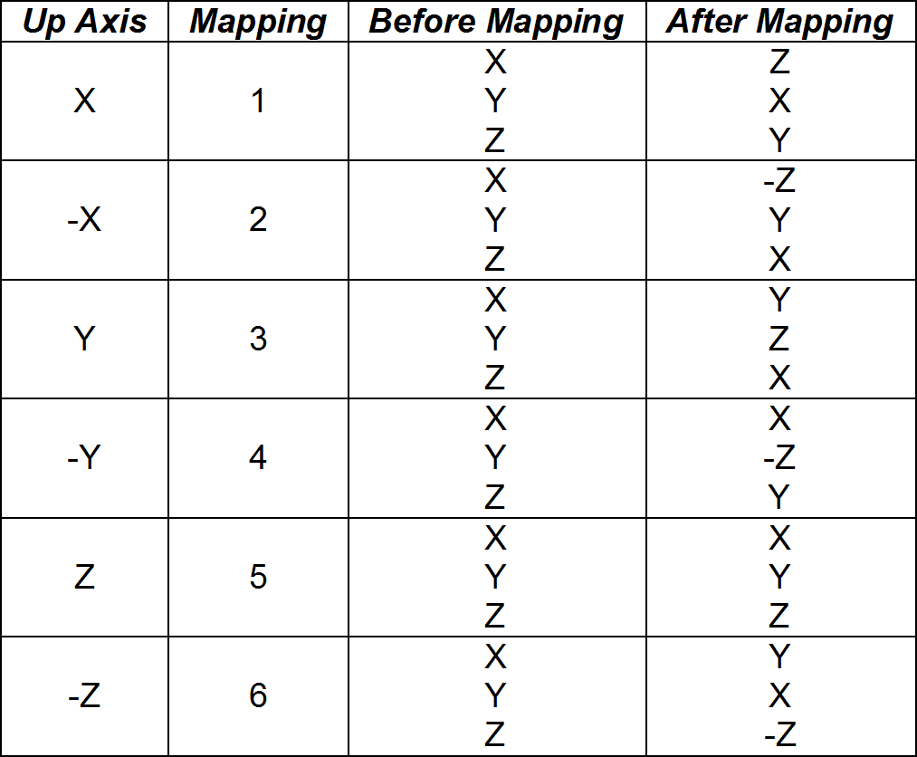 Figure 3: Mapping 6 (Light is Vehicle, Dark is IMU)
Starting with the vehicle axes (Y forward, X right, Z up), rotate around the vehicle Z axis until the vehicle Y axis is in the plane that the IMU Y axis would sweep out if rotated about its X axis (this is your Z input angle).
Z angle
Now rotate around the vehicle X axis until the Y axes match (this is your X input angle).
X angle
Now rotate around the vehicle Y axis until both the X and Z axes match (this is your Y input angle).
Y angle
Example 1 (SPAN):
VEHICLEBODYROTATION 0 0 -90 SETIMUORIENTATION 6
In this example, the IMU is mounted with its Y axis backwards, X axis to the right and Z axis down. The vehicle frame is Y axis forward, X axis right and Z axis up.
Determine the IMU mapping:
IMU Mapping = 6 (Z down)

Apply the mapping: Using the mapping (6) apply it to the IMU, the result is a new objective frame. This frame is also called the “computation” frame.
New IMU Frame

The objective is to rotate from the vehicle frame to the new objective frame.
Rotate about Z: Starting from the vehicle frame, rotate first about the Z axis (solid blue)
Z = -90 degrees
Rotate about X: Because the Y axis now matches the IMU frame there is no need to rotate about X (solid red)
X = 0 degrees
Rotate about Y: Because X and Z already match the IMU frame there is no need to rotate about Y (solid green)
Y = 0 degrees
Input into SPAN:
SETIMUORIENTATION 6V EHICLEBODYROTATION 0 0 -90
Example 2 (SPAN):
VEHICLEBODYROTATION 0 0 -90 SETIMUORIENTATION 2
In this example, the IMU is mounted with its Z axis backwards, Y axis to the right and X axis down. The vehicle frame is Y axis forward, X axis right and Z axis up.
Determine the IMU mapping:
IMU Mapping = 2 (X down)

Apply the mapping: Using the mapping (2) apply it to the IMU, the result is a new objective frame. This frame is also called the “computation” frame.
New IMU Frame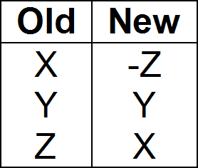
The objective is to rotate from the vehicle frame to the new objective frame.
Rotate about Z: Starting from the vehicle frame, rotate first about the Z axis (solid blue)
Z = -90 degrees

Rotate about X: Because the Y axis now matches the IMU frame there is no need to rotate about X (solid red)
X = 0 degrees
Rotate about Y: Because X and Z already match the IMU frame there is no need to rotate about Y (solid green)Y = 0 degrees
Input into SPAN:
SETIMUORIENTATION 2 VEHICLEBODYROTATION 0 0 -90