Chapter 1 Overview
SPAN’s deeply coupled Inertial Navigation System (INS) can provide accurate position, velocity and attitude of the IMU body in real-time. The accuracy of the solution depends on the IMU being used, quality of alignment (initialization) and kinematics experienced. This application note is intended to go through proper INS collection techniques as well as mention some common pit- falls that could hinder the quality of the SPAN output.
1.1 IMU Type
INS accuracy can only be as good as the IMU being used. IMUs contain a triad of accelerometers and gyroscopes that are used to measure the specific forces and rotation rates sensed by the IMU. See the SPAN brochure (www.novatel.com/assets/Documents/Papers/SPANBrochure.pdf) for information on accuracy specifications for each IMU supported by SPAN. For detailed inform- ation about the performance of each IMU, refer to the product sheet for the individual IMU (avail- able at www.novatel.com). Note that proper INS initialization and initial convergence is required in order to meet the specifications stated in the product sheets.
Chapter 2 INS Alignment
The INS alignment (initialization) is a very important factor in performance throughout the life- time of the INS filter. The alignment stage of the INS is where the initial position, velocity and attitude values used in the filter are defined. Position and velocity come from GNSS whereas atti- tude comes from one of the alignment methods available to users.
1. INS Alignment Environment
The following should be followed to have a good INS alignment:
Ensure the antenna has clear visibility of the sky.
Ensure the IMU and antenna (or antennas) are rigidly mounted to the vehicle. The GNSS signal is received at the antenna phase center whereas the IMU raw data and INS solution is computed at the IMU center of navigation. The separation between IMU and antenna must therefore be constant.
If possible, start logging data as soon as possible so that complete information on INS alignment is saved.
Mount the IMU as far as possible from external sources of vibration.
If INS performance is being hindered by vehicle vibrations, consider using dampening mounts to minimize vibrations. Use dampening mounts with caution as there is always a risk of removing actual motion.
If using a dual antenna setup, use the ALIGNMENTMODE command with either AIDED_ TRANSFER or AIDED_STATIC. This guarantees the INS alignment uses the GNSS-derived heading. (See INS Alignment Quality below for further information on alignment modes).
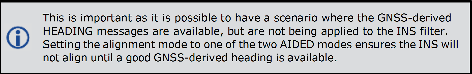
If using a dual antenna setup, ensure both antennas are far from any obstructions. The GNSS-derived heading must be verified to RTK quality levels before it is fed into the INS. Being close to obstructions lengthens this process or in some cases even prevents the update from taking place.
If using a dual-antenna setup, we recommend having both antennas at constant heights, especially in applications where larg
e pitch/roll will be experienced.1.2 INS Alignment Quality
2.2.1 INS Alignment Methods
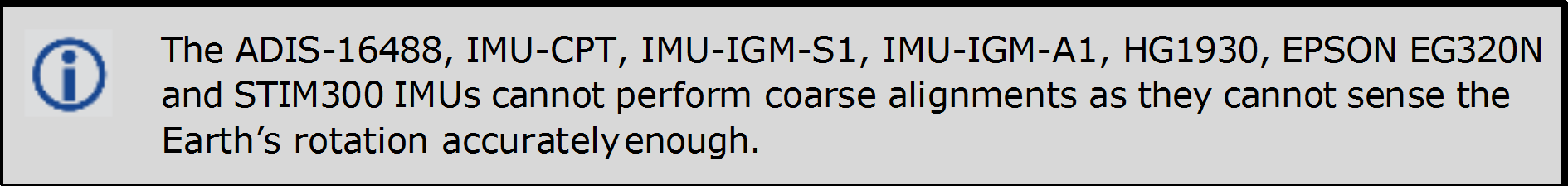
Coarse:
Provided the IMU can sense the Earth’s rotation rate, SPAN will average accelerometer and gyro- scope measurements for approximately 45 seconds to come up with the initial pitch, roll and azi- muth estimates. Note the system must stay stationary throughout this process.
Kinematic:
GNSS course over ground for three consecutive seconds is averaged provided the speed is higher than 5 m/s or the user-specified value (through the SETALIGNMENTVEL command). Kinematic alignments are not suggested for marine or aerial environments with large crab angles between the course over ground and the Vehicle frame. This applies to any environment where the defined Vehicle frame and course over ground are not aligned during the kinematic alignment procedure.
UNAIDED:
SPAN will use either a coarse(static) or kinematic alignment, whichever is available first. This command is for dual antenna installations where users do not want to align the INS via the sec- ondary antenna. In such cases, the secondary an
tenna is only used to provide heading updates to the SPAN filter.AIDED_TRANSFER:
For dual antenna installations. Pitch and roll are computed from IMU observations whereas the INS heading is set to the first RTK-quality, GNSS-derived heading from the dual antenna install- ation.
AUTOMATIC (Default):
SPAN will use the first available alignment technique to complete INS alignment.
STATIC (OEM7 Only):
INS will only align through coarse alignment.
KINEMATIC (OEM7 only):
INS will only align through kinematic alignment.
User Injected Azimuth or Attitude:
It is also possible to align the INS manually by injecting an initial heading (SETINITAZIMUTH command) or attitude (SETINITATTITUDE command). Please note these commands are meant for bench test purposes OR advanced users. The initial value and its corresponding standard devi- ation are very important for a proper INS initialization. Using either of these commands with false standard deviations (e.g., actual value has a standard deviation of 30 degrees but user inputs a standard deviation of 1 degree) has grave repercussions on filter performance.
2.3 Kinematics Immediately after INS Alignment
As has been previously mentioned, it is very important to ensure INS alignment takes place in a relatively good GNSS environment. Right after initial INS alignment it is necessary to insert the appropriate type of kinematics into the system to converge the bias-drift states being modeled. It is suggested to perform the following iterative process for a total period of three minutes:
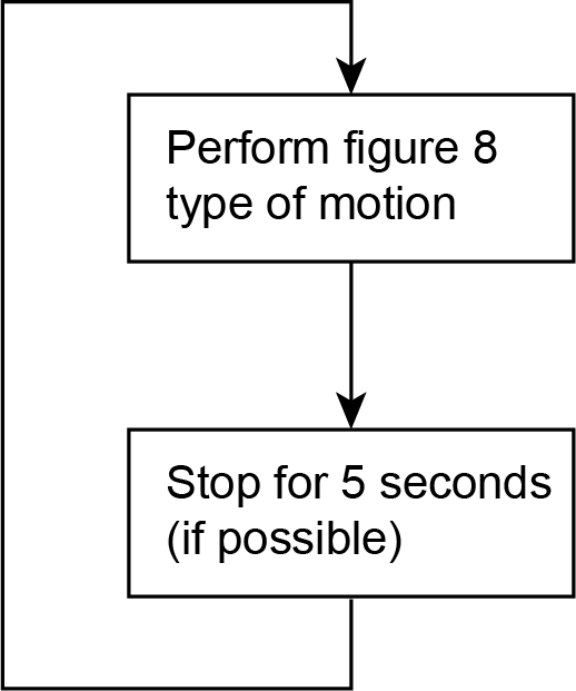
Furthermore, these types of kinematics need to be done under good sky coverage, as far as pos- sible from obstructions. Initializing the INS and entering an urban canyon immediately after is not recommended. SPAN will not behave as per product sheet levels unless it has been properly initiated and this includes the initial kinematics. If possible, start logging data from the very beginning to ensure all information is captured should there be any issues.

Chapter 3 Recommended Messages to be logged
Although every customer has a different application, and setup, it is important to always log as much information about the GNSS and INS filters and the environment in which the survey is tak- ing place. The following are the suggested messages that should be logged for every survey.
Note that the list includes all necessary messages for post-processing in Inertial Explorer.
1. Recommended SPAN Messages for OEM6
LOG RAWEPHEMB ONCHANGED
LOG GLOEPHEMERISB ONCHANGED → if tracking GLONASS
LOG GLOEPHEMERISB ONNEW → if tracking GLONASS
LOG BDSEPHEMERISB ONNEW → if tracking BeiDou LOG GALEPHEMERISB ONNEW → if tracking Galileo LOG QZSSEPHEMERISB ONNEW → if tracking QZSS
LOG HEADING2B ONNEW → if using dual antenna
LOG VERSIONB ONCE
LOG IMUTOANTOFFSETSB ONCHANGED LOG RXSTATUSB ONCHANGED
LOG RXCONFIGB ONCE
LOG VEHICLEBODYROTATIONB ONCHANGED LOG SETIMUORIENTATIONB ONCHANGED LOG RANGECMPB ONTIME 1
LOG BESTPOSB ONTIME 1
LOG BESTGNSSPOSB ONTIME 1 LOG RAWIMUSXB ONNEW
LOG INSPVAXB ONTIME 1 LOG INSUPDATEB ONNEW
2. Recommended SPAN Messages for OEM7
LOG RAWEPHEMB ONCHANGED
LOG GLOEPHEMERISB ONCHANGED → if tracking GLONASS
LOG GLOEPHEMERISB ONNEW → if tracking GLONASS
LOG BDSEPHEMERISB ONNEW → if tracking BeiDou LOG GALEPHEMERISB ONNEW → if tracking Galileo LOG QZSSEPHEMERISB ONNEW → if tracking QZSS
LOG HEADING2B ONNEW → if using dual antenna
LOG VERSIONB ONCE
LOG RXSTATUSB ONCHANGED LOG RXCONFIGB ONCE
LOG RANGECMPB ONTIME 1 LOG BESTPOSB ONTIME 1
LOG BESTGNSSPOSB ONTIME 1 LOG RAWIMUSXB ONNEW
LOG INSPVAXB ONTIME 1
LOG INSUPDATESTATUSB ONNEW LOG INSCONFIGB ONCHANGED
1. Reference Frames
Users need to be aware of two coordinate frames on SPAN on OEM7: IMU Body Frame and Vehicle Frame. The IMU Body Frame defines the orientation (reference frame) of the IMU axes marked on the IMU/enclosure. This frame will then vary depending on the orientation in which the IMU is mounted.
The second frame, the Vehicle Frame is defined as follows:
+X axis → towards right of vehicle
+Y axis → towards forward direction of vehicle
+Z axis → upwards
2. Commands
There are two main commands that need to be sent in SPAN on OEM7: SETINSTRANSLATION and SETINSROTATION. Each command has multiple options but the most important ones are those used to:
Specify the separation from the IMU center of navigation to the antenna phase centers.
Use the ANT1 and ANT2 fields of the SETINSTRANSLATION command (docs.novatel.com/OEM7/Content/SPAN_Commands/SETINSTRANSLATION.htm).
Specify the rotation from the IMU Body Frame to the Vehicle Frame (see Reference Frames above for frame definitions)