GNSS+INS Systems
As discussed, GNSS uses signals from orbiting satellites to compute position, time and velocity. GNSS navigation has excellent accuracy provided the antenna has line of sight visibility to at least four satellites. When the line of sight to satellites is blocked by obstructions such as trees or buildings, navigation becomes unreliable or impossible.
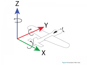
An Inertial Navigation System (INS) uses rotation and acceleration information from an Inertial Measurement Unit (IMU) to compute a relative position over time. An IMU is made up of six complimentary sensors arrayed on three orthogonal axes. On each of the three axes is coupled an accelerometer and a gyroscope. The accelerometers measure linear acceleration and the gyroscopes measure rotational acceleration. With these sensors, an IMU can measure its precise relative movement in 3D space. The INS uses these measurements to calculate position and velocity. An additional advantage of the IMU measurements is they provide an angular solution about the three axes. The INS translates this angular solution into a local attitude (roll, pitch and azimuth) solution which it can provide in addition to the position and velocity.
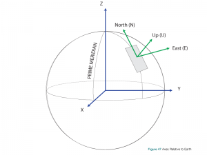
The ability of the INS to provide attitude determination is an important addition for several applications, such as aerial survey and hydrography. For example, in aerial surveys it is not only important to know where the camera was when the picture was taken, but also what angle the camera was relative to the ground.
Of course, all systems, including IMUs and therefore INS, have their own drawbacks. First, an INS provides only a relative solution from an initial start point. This initial start point must be provided to the INS. Second, and more critically, the high frequency measurements provided by the IMU include several error sources. Depending on the quality (i.e., cost/size) of the IMU these errors can be fairly large relative to the actual measurements being recorded. Navigating in 3D space with an IMU is effectively a summation (or integration) of hundreds/thousands of samples per second during which time the errors are also being accumulated. This means that an uncorrected INS system will drift from the true position quickly without an external reference. Providing an external reference to the INS allows it to estimate the errors in the IMU measurements using a mathematical filter and mitigate their effect.
That external reference can quite effectively be provided by GNSS. GNSS provides an absolute set of coordinates that can be used as the initial start point. As well, GNSS provides continuous positions and velocities thereafter which are used to update the INS filter estimates. When GNSS is compromised due to signal obstructions, the INS system can continue to navigate effectively for longer periods of time.
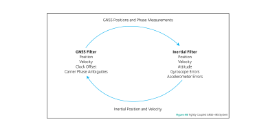
Using GNSS positions and velocities to estimate INS errors is called a ‘loosely coupled’ system. However GNSS+INS combined systems can get much more elaborate than that. A variety of terms such as ‘tightly coupled’ or ‘deeply coupled’ clearly indicate a much more symbiotic relationship between the two. In these systems, raw GNSS measurements are used directly to aid the INS and the INS can even be used as a constraint to help GNSS reacquire lost signals more quickly or reject bad signals. Figure 48 shows a simplified diagram of a tightly coupled system.
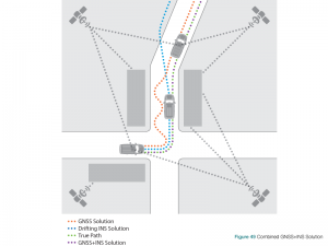
Thus, when GNSS and INS are combined, the two techniques enhance each other to provide a powerful navigation solution, as illustrated in Figure 49. When the GNSS conditions are good (line of sight to several satellites), the GNSS receiver provides accurate position and time to the navigation system. When the GNSS conditions become poor, the INS provides the position and navigation until the GNSS conditions improve.
Odometers
GNSS is not the only useful input to aid inertial navigation. For different environments, different sensors can also be added to aid the solution. A common external sensor for ground vehicles is the addition of an odometer. This provides another independent measurement of displacement and velocity that can aid the GNSS+INS navigation solution. This is mostly of use when the GNSS signal is denied, for example when traveling through a tunnel.
Vision Aided Navigation
Another potential aiding source is the use of photogrammetry, or using vision aided navigation. In a vision aided navigation system, imagery is used to provide position information to a navigation system. Images from a camera are processed by the navigation system to recognize and track objects in the environment.
There are two ways this can be used. Known surveyed camera targets can be used to generate an absolute position in a certain environment or everyday objects can be used as control points; when an object is recognized by the system, the relative change in successive images can be used to generate a relative position change of the camera in 3D space.
This means that a vision aided system can be combined with a GNSS+INS system to provide position and attitude updates to the INS when GNSS updates are not available. An example application for a vision aided navigation system is an unmanned vehicle used to carry a load from a yard into a warehouse. When the unmanned vehicle is outside, the GNSS+INS provides the navigation for the vehicle. When inside the warehouse, the vision aided system uses known features/targets within the building to provide position updates to the INS.
Sensor Fusion
A term growing in popularity in this field is ‘sensor fusion’. Increasingly it is not just GNSS, or even GNSS+INS, it is an amalgamation of any and all available information to create the most robust and accurate solution available in all conditions. All of the input technologies, GNSS, INS, cameras, odometers, digital elevation models, range sensors, etc. are taken into account.
Closing Remarks
If you want to learn more about the topic in this chapter, we have provided a list of references at the end of the book.